Toyota Supra MK3 Head Gasket Repair
Tools Required:
- Socket Wrench: 3/8" drive (flex head beneficial here), 1/2" drive
- Sockets: 10mm, 12mm, 14mm
- Deep Sockets: 12mm, 14mm
- Socket Extensions: 3in, 6in
- Wrenches: 12mm, 14mm
- Screwdriver: Phillips
- Breaker Bar
- Torque Wrench (75-100 ft-lbs)
- Block Thread Tap (ARP part no: 912-0006)
- Gasket scraper or razor scraper
- 10mm hex bit socket
Parts Required:
- New Head Gasket
- Gasket Kit (Top end)
- Toyota FIPG or Permatex "The Right Stuff"
- Optional:
- ARP Head Bolts/Studs (14mm deep socket 12 pt required)
The largest known flaw of the A70 Toyota Supra is the 7M’s head gasket. Somehow Toyota failed to realize their specified torque for the head gasket was too low and that it would lead to premature failure in many engines. Today, many years after the last A70 rolled off the production floor it is extremely difficult to find a MK3 Supra which has not had a head gasket failure. Anyone buying a MK3 Supra needs to be well aware of this chronic issue and needs to know how to fix it. The proper fix isn’t extremely difficult and may not be as expensive as one would think.
Things to consider:
-
Head Machining:
You will need to machine the head for it to seal with the new gasket. This is a great time to have a basic rebuild done. Most machinists wont charge more than a few hundred dollars to do a basic valve job on a 7M. If you can afford it go ahead and get a valve job. At the very least you should replace the valve stem seals. If these are leaking the engine will smoke and it’s not easy to change these seals once you get the head back on.
-
Head Hardness:
If the aluminum head of a 7M is overheated it can anneal and soften. If this happens, the head is not worth re-using. An easy indication of a soft head is stripped bolt holes for the manifolds, camshafts and other mounting holes on the head. If more than a couple holes are stripped the aluminum in the head is likely too soft for reliable use, even if you baby the car. Sorry, time to hunt for a used head.
-
Power Goal:
The stock head gasket is great for factory power and beyond. If you’re aiming for 350whp or more you may want to change your approach and opt for a metal head gasket. I’ve used a stock head gasket on all my builds and never had the gasket blow again using ARP head bolts or head studs with a combined 50k miles of driving aggressively.
-
Metal Head Gaskets:
These REQUIRE machine work on the block and head. You cannot simply remove the head to install an MHG. Let’s repeat this; MHG’s REQUIRE machine work on the block to be reliable. The manufacturers of every Metal Head Gasket state the surface RA of the mating surfaces must be low (below 50 ra). This means machine work. Every. Single. Time. If you cannot remove the block for machining then you’re limited to a factory style composite head gasket. Lapping the block in car is difficult to do without inducing variation in the height of the deck surface. The simple rule is if you can’t pull the block for machine work, you can’t use an MHG.
-
Hardware:
Toyota head bolts are not TTY or one time use bolts, but many people choose to upgrade to ARP hardware just in case. Given the cost of tearing down a motor I always opt to buy ARP head studs and play it safe. The ARP hardware is strong and the studs give the benefit of a more accurate torque.
-
Chasing Threads:
On every BHG fix you should plan on “chasing” the threads in the block. This involves using a special tap that cleans the threads in the block and helps installing the head studs/bolts very easy and smooth. The special tap is around $50-60 shipped and this easy step will save you a lot of potential headache. For the 7M head bolts the size is 12x1.25mm. A normal tap can be used, but you run the risk of damaging the block threads and cutting extra material. Please do it right, chase the threads.
Other Gaskets:
You’ll be removing most everything that has a gasket on the top end to repair a head gasket so you will need a lot of other gaskets. Many aftermarket vendors sell gasket kits for 1/10th the cost of genuine Toyota gaskets. If you’re on a budget and just need to get the car running, these kits may fit the bill, but I’d advise using genuine Toyota gaskets for at least the exhaust and throttle body gaskets. The exhaust gaskets are supposed to be metal and I’ve noticed a significant difference in quality between genuine Toyota and the cheap aftermarket options. Exhaust leaks are annoying and fixing them after the fact can be a pain.
Diagnosis

Figuring out if you have a Blown Head Gasket can be tough in some instances. Classic signs are:

- Milky Oil (can usually be seen under oil filler cap)
- Brown Coolant
- Constant overflow of your coolant reservoir
- Coolant leakage at the Head Gasket seam
- Engine Overheating
If you are unsure if you have a BHG you can try a couple things. One is a block test kit or a combustion gas test kit. This kit tries to pull air through your cooling system. If the kit can pull exhaust gas through your cooling system an indicator fluid changes color. Another method is a leak down test. This involves progressing through your motor looking for the source of an air leak. Once you determine you have a BHG or if you know you want to go for big power, it’s time to fix the problem.
Removal
Detailed steps/pictures for N/A

01Disconnect the negative terminal from the battery and push it to the side of the battery.
02Remove the air filter, box and accordion hose. This includes a couple hose clamps on the accordion hose, a couple vacuum hoses on the bottom of the accordion, two hoses on the top, one connector on the Air Meter, 3 bolts on the factory filter box and one on the air meter mount bracket.
03Drain most or all the coolant. Most the coolant can be removed from the radiator. Either jack up the car or reach under and drain the coolant into a large container. You’ll need to drain about a gallon at least.
04Remove the Throttle Body (TB) and linkage. This involves 4 12mm bolts on the TB, 2 brackets on either side of the TB, 3-5 vacuum hoses, two coolant hoses, one TPS connector, throttle linkage and one large crankcase vent hose.


05Remove the Alternator. This involves loosening the large pivot bolt (14mm), loosening and removing the adjustment bolt, sliding off the belt and then removing the pivot bolt and alternator.
06Remove the Y-Piece of the Intake. 6 12mm bolts mount the Y-piece to the plenum. The Y-piece is also held by a couple brackets attached to the head underneath.
07Unbolt the Intake Plenum. There are many 12mm bolts that are hidden here. Be patient and reference the following diagram to help out with their locations. You’ll also need to unbolt the EGR, cold start injector and ground strap.
08Remove the Fuel Rail. This will require removing a couple fuel “banjo” bolts. The lines *might* have pressurized fuel so be careful when breaking the banjo bolts loose. It’s a good idea to have a shop rag/towel under the bolts to catch any stray fuel. Carefully pull out the fuel rail and injectors and set them aside. Treat the injectors with extra care and don’t lose any of the insulators (cushions) and inspect the injectors for bad O-rings.

09Remove the intake manifold. You have two options here: Remove the harness from the manifold completely and use the manifold to help lift the head out later or just unbolt it and place off to the driver’s side leaving the harness alone.
10Remove the Exhaust Manifold. For non-turbo cars this is easy. Simply remove the shields and then the manifold. You’ll need a deep socket for the manifold studs. For turbo cars this step is much more involved. You’ll need to remove the shields, turbo, oil lines and then the manifold.
11Remove the Distributor/CPS. This has one lonely bolt. Once the adjustment bolt is removed the distributor should slide out, but may need some persuasion.
12Remove the Rear Coolant Hoses. One hose is a small 90 degree hose on the exhaust side. The other is in the center of the back of the head and goes to the heater valve on the passenger firewall.
13Remove the Front Timing Cover. This is the piece that has the 7M-G[T]E sticker. These should be 10mm bolts.
14Remove the Timing Belt from the pulleys. Loosen the tensioner bolt and use a pry bar or screwdriver to push the tensioner loose then tighten the tensioner bolt again. If you’re replacing the timing belt go ahead and remove the lower cover as well. The timing belt can now be removed from the cam gears (or removed completely if you took off the lower cover.)

15Remove the Cam Gears. This step benefits from a special tool, but it isn’t absolutely needed. The gears must be held in place while the bolt in center is broken loose. A 10mm deep socket might work to hold the gears in place if the socket is placed on one of the rear timing cover’s bolts through the cam gears. Be careful not to lose the pins in the gears.
16Remove the Water Outlet Housing. The housing has three 12mm bolts

17Remove the Head Bolts. NOTE: THESE MUST BE REMOVED IN THE CORRECT ORDER. The correct pattern is an x shape starting at the outside moving in to the center. The first bolt is the front intake side. This requires a 10mm inverse hex and at least a short extension.
18Remove the Cylinder Head. This is the fun part. The head is best removed as a two person job, but one person can remove it with some good upper body strength.
Inspection, Analysis and Maintenance
01Head Gasket. Usually a Blown Head Gasket leaves the gasket in an obviously damaged condition. Most common is a deformation of the ring lining the cylinder outwards into the water jackets. Take a look at the gasket and search for the damaged area.
02Head. Check the sealing side of the head for any damage in the surface. Don’t bother cleaning the surface as it needs to be machined flat before you put it back on. Check the valves and the top of the combustion chambers for any damage. If you see even a tiny crack the head may be unusable. If you don’t find anything obviously wrong, drop the head off at a machinist for at least a cleaning and mill. If you can afford it a valve job with stem seal replacement is a good idea. Ask if the machinist can perform a hardness test. A soft head is a death sentence. A common sign of a soft head is bolt holes which strip. The exhaust manifold studs are generally the first to go.
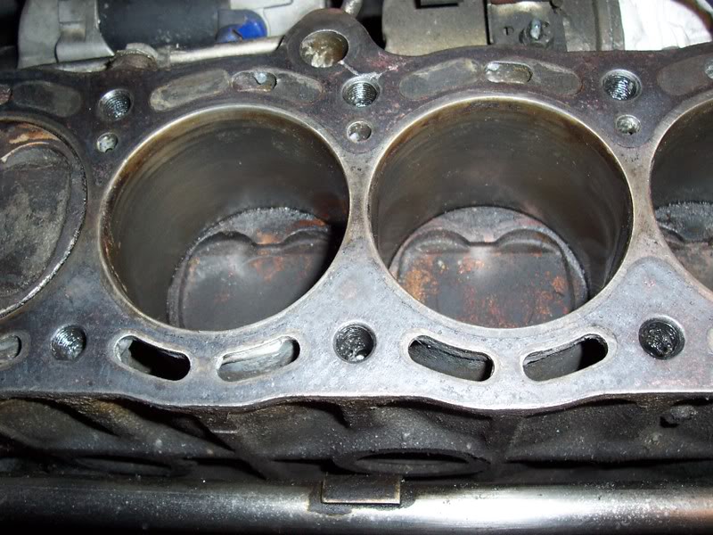
03Block. The block will likely have gasket material stuck to the deck surface. This material needs to be carefully removed before the head goes back on. A gasket scraper or razor scraper does the job well. Spend plenty of time cleaning the deck surface. If the surface isn’t clean you’ll have another blown head gasket soon. Do not try to sand or polish the deck surface. Those processes are likely to create shallow valleys which will not seal.
04Replace the Rear Heater Union and Hose. These parts can create a huge headache down the road. I think it’s worthwhile to replace this every time you perform a head gasket repair. Buy a new union and a new hose and save yourself a lot of hassle down the road. You’ll never have an easier chance to replace them once the head is reinstalled. The hose is around $10 and the union is about the same. It’s some of the best $20 you can spend during this job.
05Replace the Cam Seals and all other gaskets/seals that come with the top end gasket kits.
Installation
01Chase/Clean the Block Threads. If you have a thread cleaning tap from ARP now is the time to use it. It’s generally a bad idea to use a regular tap to clean threads because you’ll remove extra material and weaken the threads. Kit # 912-0006 from ARP is an M12 - 1.25 tap that’s the correct size for a 7M.

02Apply Form In Place Gasket (FIPG)/Permatex “The Right Stuff” to the seams of the block and rear timing plate.
03Install the Head Gasket. The block surface should be very clean. Lay the gasket down on the block with the head guide pins installed in the block. You can use copper spray here if you would like, but it is not required.
04Install the Head. This is best done by two people. The clean, machined head should be placed down very carefully and accurately. It will fall into place once the guide pins line up with the head.
05Install the Head Hardware. If you opted for ARP hardware crack open that package and get ready to install the new bolts/studs. For ARP hardware you need to the cams removed to install the ARP nuts. You also must use the ARP supplied lubricant to achieve the proper torque when tightening. The tightening sequence is CRITICAL. You must begin in the center and work your way out to prevent warping the head material. Install the cams if they were removed. They also should be shimmed correctly if the machine shop didn’t already do that.
06Follow all removal steps in reverse.

Leave a comment